|
Modeling Basics
When CO2 is injected into a subsurface rock formation, it forms a separate free, supercritical phase which is commonly referred to as the CO2 plume. The CO2 phase is less dense than the formation water and will therefore start to rise upwards. CO2 is typically injected under a sealing rock, in which the capillary pressure inside pore throats is greater than the buoyancy pressure of the CO2. The seal will form a top surface on the permeable rock and prevent the direct upward movement of CO2. If the top seal is sloping, the CO2 will form a thin layer underneath that slowly migrates in the upslope direction.
Trapping mechanismsIn general there are four basic mechanisms that will prevent the CO2 from leaking back to the atmosphere:
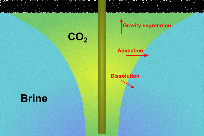
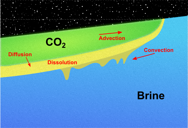
These processes will take place across a wide span of time scales. MRST-co2lab focusses primarily on the first three mechanisms, which are often assumed to take place on a somewhat shorter time scale than mineral trapping. Upper bounds on the structural trapping can be determined at a low computational cost by geometrical and topological algorithms that only utilize a description of the surface that separates the aquifer from the overlying caprock. For more details, consult our discussion of structural trapping and spill-point analysis. Modeling injection and migrationTo also describe residual and solubility trapping, one generally has to solve a coupled system of partial differential equations that describe the conservation of the fluid phases and chemical components that are present in the aquifer. In their simplest form, these equations describe a system of two fluid phases, supercritical CO2 and brine. How these fluid phases flow together and interact during the injection and migration stages is governed by delicate balances of a number of physical mechanisms (see the Figure 1). The balances may change with time and spatial location, and resolving the long-term CO2 migration is a challenging multiscale problem that involves a large disparity in spatial and temporal scales.
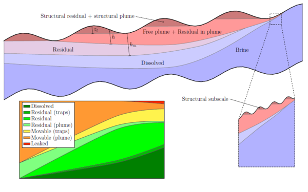
Vertical equilibrium modelsCO2 is very mobile and can travel large distances, but the flow is usually confined to thin layers underneath a sealing caprock or other low-permeable vertical barriers. A typical saline aquifer considered for CO2 storage can be viewed as a thin, slightly inclined sheet that spans thousands of square kilometers. This, in combination with differences in density between the supercritical CO2 plume and the resident brine, means that the vertical fluid segregation will be almost instantaneous compared with the up-dip migration. The tendency of forming a relative flat fluid interface is an effect of the pressure distribution, which in turn depends strongly on the flow in the vertical direction, particularly near the interface. The vertical fluid distribution must also be accurately represented to avoid introducing large errors in the forecast of the updip migration. The thin plume and sharp transition between CO2 and brine means that high vertical resolution is required to compute the vertical phase distribution. In MRST-co2lab, the primary assumption is that the flow system is in vertical equilibrium so that the vertical distribution of fluid phases can be determined from analytical expressions. One can now integrate the flow equations vertically to obtain a reduced model. This not only reduces the number of spatial dimensions, and hence the required number of grid cells, but will also lessens the coupling between pressure and fluid transport and improves the characteristic time constants of the problem. As a results, so-called vertical-equilibrium simulators will typically be orders of magnitude faster and consume signficantly less memory than conventional 3D simulators (which are also available in MRST). Using these vertical-equilbrium models, it is easy to simulate pressure buildup and plume migration, and provide reliable forecasts of the various trapping mechanisms, e.g., as illustrated in Figure 2. You can read more about VE models here or in one of our papers.
|
||||||||