|
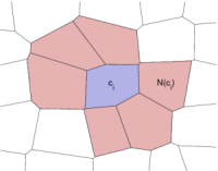
Upgridding by Amalgamation
Geological models are becoming increasingly large and detailed to account for heterogeneous structures on different spatial scales. To obtain simulation models that are computationally tractable, it is common to remove spatial detail from the geological description by upscaling. We have developed an algorithmic framework that consists of a set of modular components that can be combined in different ways to create flow-based coarse grids that are ideal for computing fluid transport. The fundamental characteristic of all algorithms is that coarse blocks are generated by amalgamating cells from the original fine grid, with a cell-wise indicator function guiding the amalgamation directions and the new grid resolution.
Example: Non-Uniform Coarsening
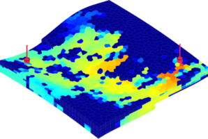
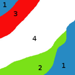
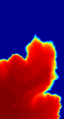
Flow-based coarsening generally gives improved accuracy in the computation of fluid transport, as shown in the figure below. We consider an extruded PEBI model with petrophysical parameters sampled from Layers 50-60 of the SPE10 benchmark and a diagonal displacement crated by placing an injector and a producer in opposite corners. The figure compares the saturation distribution after one pore-volume of water has been injected, simulated on three different grids. We observe that the METIS grid has too large blocks in the flow channel to capture the flow well, while the time-of-flight grid to a large degree matches the flow pattern from the original fine grid.
References:
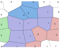
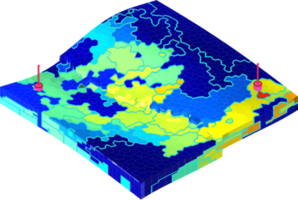
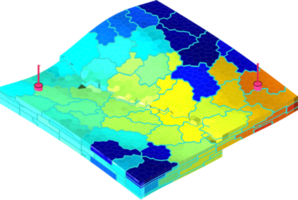
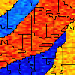
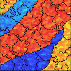
Example: Hybrid GridsThe amalgamation framework is quite general and contains a large number of different coarsening methods as special cases. Each particular method can be expressed by combining the generic filters for merging and refining blocks with different a priori partitions and indicator functions. In the figure below, we show grids that are generated using a combination of structured topological and flow-based partitions.
The coarsening can also be constrained to various geological features. In the figure below we use information of facies to constrain each coarse block so that it contains only one facies.
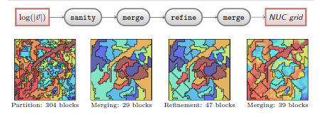
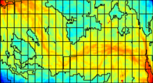
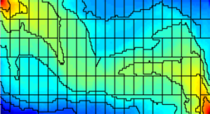
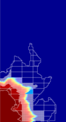
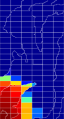
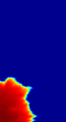
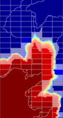
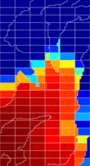
Example: Adaptive GridsBecause the all coarse grids created by agglomeration of cells from a fine grid are represented using a partition vector, it is (almost) straightforward to add dynamical adaptivity. We generate a coarse grid based on the time-of-flight indicator intersected with a uniform topological partitioning, as shown in the figure above. Local refinement, down to the resolution of the original grid, is added in regions near the displacement front. Cells that have time-of-flight values a certain fraction larger than those near the displacement front will likely belong to the unswept zone and are therefore merged into a single coarse block. Moreover, a band of blocks with intermediate resolution is kept ahead of the displacement front (measured in time-of-flight) to localise the search for regions that need to be refined in the next step and as a precaution when multiple time steps are computed without updating the grid. The figure below shows examples the adaptive grids for Layer 22 from the SPE10 model. For comparison, we also show the saturation profiles on the original and on a corresponding static coarse grid.
Examples of locally adapted grids for Layer 22 of the SPE10 model. The three plots to the left show saturation profiles after 0.1 pore volumes have been injected, whereas the rightmost plots show saturations at 0.5 PVI. |
||||||||||||||||||||||||||