
CENBIO - Enabling sustainable and cost-efficient bioenergy in Norway
SP2 - Conversion mechanisms
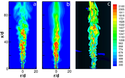
Numerical Simulations of the Sandia Flame D Using the Eddy Dissipation Concept
Important aspects to mention from the work in SP2 is the mix of long-term challenges together with short-term "troubleshooting" discussions. The methods used span from experiments in laboratory-scale reactors, advanced measurement equipment and analytical methods, to investigations at full-scale facilities, and additionally modelling as well as desk studies. In 2015 there has been strong involvement of CenBio industry in both work at full-scale plants and in writing articles. Non-CenBio actors have been involved whenever necessary for the benefit of CenBio.
Concrete 2015 achievements in SP2
- Ash deposits collection and advanced analysis at two partners, EGE and Statkraft Varme, in order to propose abatement methods. Two conference articles summarise the main results
- Full-scale bioheat plant measurement campaign to map the concentrations of a number of gaseous species inside the combustion chamber, at different locations and at varying operating conditions in order to better understand formation mechanisms
- CFD modelling activity on the aforementioned plant, where the essential part of the work in 2015 has been on improving the model of the conversion of the fuel bed
- In-depth study of selected ash-forming elements applied to the Energos gasification process using thermodynamic modelling, the main goal being a better control over the corrosion risk
- Study of the population dynamics of biogas reactors at laboratory scale
- Quang-Vu Bach (NTNU) defended his PhD thesis on wet torrefaction in January 2015
WP2.1 - Combustion
Measurement campaign and combustion modelling at Statkraft Varme Marienborg
The work in CenBio at the Statkraft Varme Marienborg plant has been performed to better understand and hence improve plant operation. The work has been done as a cooperation between SINTEF Energy Research, NTNU and Statkraft Varme AS, and has consisted of two main activities: measurement campaigns and combustion modelling.
Biomass combustion plants in Norway are facing stricter emission regulations and lower profitability, mostly due to low energy prices. Hence, performance optimisation through improved combustion process control and/or retrofitting becomes very attractive to existing plants. However, the trial and error approach usually applied by the plant operator is time and cost consuming, and offers no guarantee of success. Increased combustion process knowledge on the other hand has the potential to provide the necessary input to improved combustion control strategies, being operational aimed or design/retrofit aimed. The outcome of the improved control strategies can be lower emission levels, improved efficiencies, increased plant capacity or/and reduced maintenance costs.
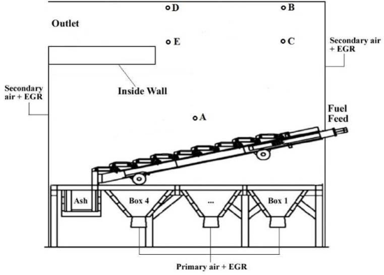
In this study, a measurement campaign was carried out at a 10 MW grate fired plant burning wood briquettes – the Statkraft Varme Marienborg plant in Trondheim, see schematic picture in Figure 1. The aim of the measurement campaign was to map the concentrations of a number of gaseous species inside the combustion chamber, at different locations and at varying operating conditions. A specially constructed probe was employed to extract gas at different locations close to the fuel bed, in the freeboard and at the combustion chamber exit. A Fourier Transform Infrared Spectrometry (FTIR) instrument was used for gas measurements, including NOx precursors/intermediates. In addition, a gas chromatographer (GC) quantified the remaining main species as well as provided a validation for some of the FTIR measurements. During the campaign the plant load was varied between 4.5 and 10.5 MW.
|
|
Figure 1: Schematic of Statkraft Varme Marienborg biomass grate furnace (including measuring ports). |
The measurements taken just above the bed showed high concentration of devolatilisation products. These products increased with increasing thermal input. In addition, NOx precursors, HCN and NH3 increased with increasing load. However, the measured ammonia concentration was lower than expected and could be caused by adsorption in the filter unit. Gas measurements were also taken after secondary air injection (positions B and C) and at the outlet of the combustion chamber (positions D and E). For low thermal load, unburnt compounds were still present at position B and at even higher concentrations further inside the boiler (position C). This is reflected by the high CO concentration. Higher thermal input resulted in better combustion efficiency, however the CO concentration still increased when the probe was positioned further into the boiler (positions E and C). NO concentrations at all positions (B, C, D and E) were stable.
Together with continuously measured flue gas concentrations and plant operational data, the measurements provide valuable information for combustion control strategies as well as for validation of modelling approaches, or input to these. Computational Fluid Dynamics (CFD) is the ultimate design tool for bioenergy plant combustion and heat transfer sections, however, cost-effective sub-models need to be developed. NTNU has worked on developing a comprehensive CFD model with the open source software package OpenFOAM including detailed descriptions of the physical processes involved, the NELLI code. OpenFOAM enables full access to sub-models on all levels (particle models, kinetics etc.).
The essential part of the work in 2015 has been on improving the model of the conversion of the fuel bed. Previously a full Eulerian-Lagrangian approach has been used, where each individual biomass particle is tracked throughout the simulations. However, this approach becomes extremely cumbersome when dealing with large sized systems as well as uncertainties about detailed initial conditions for the simulations are restricting reliable results. In order to resolve sufficient details in a computationally inexpensive manner, efforts have now been made to develop a complete new solver in OpenFOAM to enable that the fuel bed can be considered as a continuum and modelled as a porous medium. This will increase the flexibility of NELLI, and broaden the applicability of the code to industrially relevant systems such as commonly used grate fired furnaces. The model will be validated with the measured data obtained from the 10 MW biomass grate furnace at Statkraft's Marienborg biomass combustion plant described previously, and will be presented at the European Biomass Conference and Exhibition (EUBCE) in June 2016. The measurement campaign carried out provides useful data for CFD modelling of the plant, both for modelling of the fuel bed, the freeboard and flue gas emission levels.
Ash deposits – Conference article to IConBM2016
This work on ash deposits has been a cooperation between sub-projects (SP1 and SP2) and several R&D and industry CenBio partners: SINTEF-ER, SINTEF-MC and EGE Oslo. The results from the work was summarised in a conference article sent to IConBM2016.
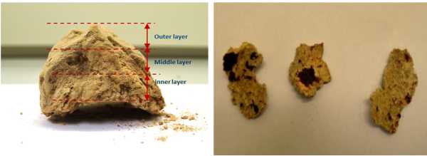
MSW is a mixture of inhomogeneous materials with large proportions of ash that contains high concentrations of sulphur, chlorine, alkali and alkali earth metals, and minor amounts of heavy metals like lead and zinc. During incineration, these ash-forming elements will volatilise and transform through complex chemical and physical processes, and will be transported together with particles from the fuel bed in the flue gas. These volatiles and fine ash/fuel particles result in formation of deposits on heat transfer surfaces in the convective section of the boiler. Due to further accumulation and sintering of the deposits, the heat transfer from the flue gas to the heat transfer tubes can be significantly reduced, causing reduced energy efficiency of the plant. Additionally, excessive formation of corrosive deposits will also lead to corrosion of heat transfer tubes and will increase maintenance costs (reduce components' lifetime) and unplanned shutdowns. Therefore, detailed characterisation and studies on deposits from MSW incineration plants are critical to understand and predict ash transformation and the related deposits formation process. A picture of the bulk deposits as received is shown in Figure 2.
|
|
Figure 2: Photos of bulk deposit (left) and inner layer (right). |
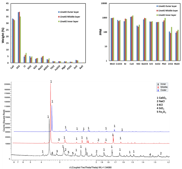
Chemical and mineralogical compositions of deposits from the EGE Oslo Klemetsrud WtE plant have been characterised (see Figure 3 for analysis results). Ash deposits are analysed via a combination of scanning electron microscopy equipped with energy dispersive X-ray spectroscopy (SEM-EDX), X-ray powder diffraction (XRD) and X-ray fluorescence (XRF). The results show that the deposits formed have a clear-layered structure along the thickness, in terms of density and morphology. The combination of different analytical techniques is also capable of characterising chemical and mineralogical compositions of the collected deposits along the thickness of the deposits. The key ash transformation and chemical reactions involved in deposits formation in this plant are investigated. The primary deposits, mainly melted sulphates and chlorides, initially build on heat transfer tube surfaces and act as a sticking surface to particles and aerosols passing by. The secondary deposits are dominated by calcium sulphates, silicates, and calcium and silicon oxides formed in the combustion chamber. Within the deposits, interactions of different mineralogical phases take place, leading to formation of new chemicals and further sintering of deposits.
Such advanced analysis and characterisation studies are seldom carried out on industrial samples and bring valuable information on the mechanisms at work and the parameters of importance.
|
|
Figure 3: Chemical compositions of different parts of deposit collected from line #2 (top). Mineralogical composition different parts of deposit sample collected from line #2 (bottom). |
Ash deposits from Statkraft Varme
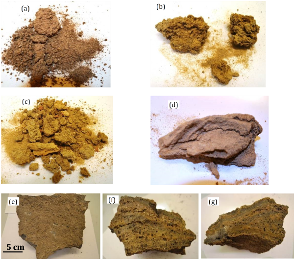
In the present work, the chemical and mineralogical compositions of ash deposits collected from the Statkraft Varme Heimdal WtE plant are characterised and evaluated (see also previous section for similar work at EGE Oslo).The ash samples have been collected vertically from bottom to top of the right side wall of the primary combustion chamber. The collected ash samples include ash slag formed in the vicinity of the grate and ash deposits formed on the boiler wall, see Figure 4 for ash and deposit samples.
Ash samples are analysed via X-ray fluorescence (XRF) and a scanning electron microscopy equipped with energy dispersive X-ray spectroscopy (SEM-EDX), in order to obtain both bulk and micro chemical compositions. In addition, mineralogical phases in the ash samples are characterised via X-Ray powder diffraction (XRD).
The slag sample has completely melted into a dense clinker that has a clear layer structure along the thickness. SEM-EDX spot analyses on each layer reveal clear differences in chemical compositions and associations of the detected chemical elements. The ash slag formation process is investigated via a combination of SEM-EDX and mapping analyses on all layers. Analyses of ash deposits collected from different locations showed that they contain mixtures of salts, silicates and oxides formed during combustion of the MSW. However, concentrations of certain elements are different for ash deposits sampled from different locations, indicating partitioning differences during the transportation from bottom to top of the primary combustion chamber. Accordingly, different final disposal/use methods could be considered for the ash deposits collected from different locations in the plant.
|
|
Figure 4: Photos of general view of (a) deposit sample #1, (b) close view of some coarse lumps, (c) general view deposit sample #2, (d) close view of some coarse lumps with layered structure, (e-g) show photos of slag sample from (e) top-down view, (f) left side view, (g) front side view. |
The macroscopic appearance and microstructure of the three samples were also evaluated. The results show that, compared to the ash deposit #1 collected from the lower section of the combustion chamber, the ash deposit #2 collected at the top of the combustion chamber contains finer particles and molten phases. The chemical and mineralogical compositions of the three samples were determined by XRF and XRD analysis, respectively. The ash deposit #2 is rich in Ca, S, Cl and alkali metals, while the ash deposit #1 contains mainly non- and less volatile Si, Ca, Al and Fe. Differences in chemical compositions of the two deposit samples are mainly related to different transformations, partitioning and chemical reactions of ash forming elements in the MSW. XRD analyses show that the ash deposit #1 contains mainly akermanite and wollastonite, while the ash deposit #2 is rich in sulphates. SEM-EDX analyses agree well with the XRF and XRD analysis results. The ash deposit #2 is formed due to condensation, agglomeration and sintering of sulphates, which are rich in Ca, S, Cl and alkali metals. Formation of the ash deposit #1 is attributed to accumulation and aggregation of rather large particles containing high temperature materials. Finally, the slag sample collected close to the grate has a dense and layered structure, which is formed due to formation, accumulation and melting of silicates.
WP2.2 - Gasification
Conference presentation on S-Cl-Na-K chemistry during MSW gasification: cooperation between Energos and SINTEF-ER
Using Municipal Solid Waste (MSW) as an energy source (aka WtE - Waste-to-Energy or EfW - Energy from Waste), with a significant fraction being of biogenic origin and therewith renewable, is a well-established practice in several EU countries as well as parts of Asia and North America. The most common technological solution is combustion on a moving grate with heat and/or power production. However, according to Eurostat, 37% of EU-27 MSW (i.e. in the order of 90 million tons) are neither material- nor energy-recovered but currently landfilled. As illustrated by the EU Waste Hierarchy, WtE is, combined with material recycling and biological treatment, an efficient and well-regulated waste management alternative, but sometimes suffers from a negative public perception. In this context, innovative thermal solutions, such as MSW gasification may both avoid such pitfalls as well as offer additional advantages.
However, gasification is not exempt from operational challenges with ash-related ones (corrosion, fouling, slagging) being of prime importance. These challenges have an impact on the plant overall performance and hence profitability.
Using Energos technology operational as case study, this work proposes a thermodynamic study on the chemistry of selected ash-forming elements (alkalis, i.e. Sodium Na and Potassium K), Sulphur (S) and Chlorine (Cl) during gasification as they are central in the aforementioned ash-related challenges. Energos technology is a grate-based MSW gasification concept. The principle is a two-stage process where gasification (syngas production) is directly followed by combustion of the syngas to produce heat/power. Several Energos plants are currently in commercial operation or under procurement/construction.
Little attention has been given to alkalis at reducing conditions in thermal systems, except for a few studies. During combustion, various transformations are taking place involving ash compounds and reducing conditions may affect both speciation and phase distribution. To optimise plant operation and develop gasification models, it is important to understand both the fluid dynamics and thermal processes. A first beneficial step to better comprehend the latter is the use of thermodynamic equilibrium methods. Thermodynamic equilibrium calculations have proven their relevance in a variety of applications and despite limitations; they provide valuable information on chemical trends. Such calculations are a powerful tool and, at present, represent the most practical computational possibility for investigating elemental chemistry in a multicomponent and multi-phase complex thermal system. This study presents the Na-K-S-Cl-containing products and chemical trends at varying temperature with focus on the formation of corrosive compounds during MSW gasification.
This succinct thermodynamic study addresses the waste gasification chemistry of four chemical elements involved in ash-related challenges, i.e. Na, K, S and Cl. At typical temperatures for the process studied, the following main trends have been observed: (1) the phase distribution of these elements may change abruptly, i.e. within a narrow temperature range; (2) the main practical outcome of point 1 is that it will be difficult to optimise a given process giving the versatility of chemistry with temperature: However, stable operating conditions are preferable. Different approaches exist to abate ash-related challenges, but selecting one (or a combination) is complex and should be based on both practical and economic considerations.
Detailed biomass particle thermal degradation model in Eulerian-Lagrangian CFD modelling
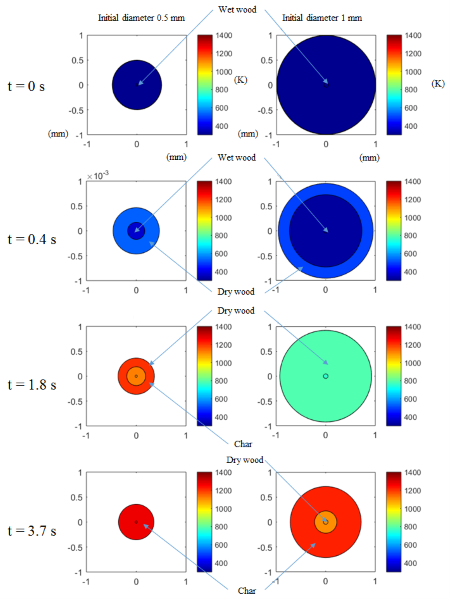
Devolatilisation is a crucial step in the processes of thermochemical conversion of solid fuels, in particular, biomass, which typically has a high volatile matter content. Depending on Biot numbers, the thermal behaviour of biomass particles in the devolatilisation process may differ significantly. As a result, thermal degradation of the biomass is determined by whether the particles are thermally thick or thin. Due to the inherent physical properties, it is difficult to prepare small particles of biomass especially for the lignocellulosic biomass. Therefore, the Biot numbers of biomass particles in a high-temperature devolatilisation process may not be sufficiently low to neglect temperature gradients within particles. In order to simulate the thermochemical degradation of thermally thick biomass particles, a sub-model proposed by Ström and Thunman has been implemented in the Eulerian-Lagrangian CFD model developed at NTNU within the OpenFOAM framework (NELLI). The implemented sub-model for thermally thick particles treats a biomass particle with three distinct layers: moist wood, dry wood, and char. Chemical and physical changes can then be modelled accordingly in each layer as a function of time. Figure 1. shows the evolution of two differently sized particles. In the dry wood layer, the devolatilisation is simulated by a primary and a secondary stage. In the primary stage, the biomass decomposes to a mixture of light gases, tar, and char.
The tar may also decompose to light gases through the secondary decomposition. The neighbouring layers exchange heat and mass. In this manner, the gradients of temperature and species within a particle can be predicted. This is work in progress and will continue in 2016. The performance of the CFD model is examined by a detailed comparison with experimental data from a drop tube reactor, and has been presented at the European Biomass Conference and Exhibition (EUBCE) in June 2016.
|
Figure 1: Time evolution and the thermochemical degradation of thermally thick biomass particles of two differently sized particles. |
WP2.3 - Pyrolysis
In 2015, pyrolysis-related activities have been carried out through the (non-CenBio financed) EnergiX KPN project BioCarb+ (main focus: carbonisation), led by SINTEF-ER.
WP2.4 - Anaerobic digestion
Microbial population dynamics
The population dynamics of two x 2 parallel biogas reactors at laboratory scale initially operating close to the edge of stability (i.e. overloaded with substrates) were studied for twelve weeks. The reactors were fed with a mixture of whey permeate, fish ensilage and cow manure. Loading rate of whey permeate was further increased in one of each parallel until pH suddenly dropped below six, causing a drop in digester's activity. The rescue action consisted of replacing 30% of digestate with cow manure and effluent (produced digestate) from the previous 10 days. When activity recovered, loading was stepwise increased in all reactors. It turned out that only the reactors subjected to temporary overloading and subsequent rescue achieved the capacity to sustain continuous high loading at 9 g COD L-1 day-1. One additional reactor was running as control at 5 g COD L-1 day-1.
In order to see if there was any correlation between population dynamics and process performance, approximately 50 bacterial orders were classified and more than 170 bacterial genera were characterised (using Roche Ultra-deep pyrosequencing). Results indicate that the rescue action had a notable impact on the community composition and that less than 1% relative abundance at genus level may be significant for process performance.
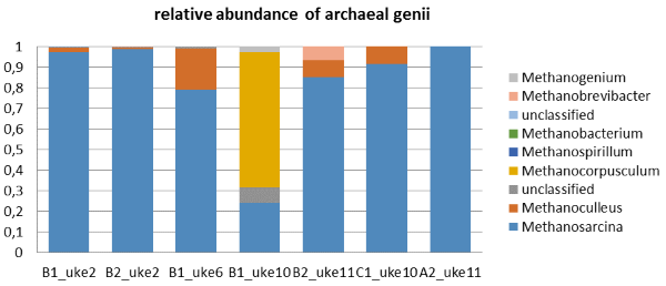
Concerning methanogen population, the number of sequences assigned to Archaea (see Figure 1) tends to be reduced from week 2 to 11 from about 4% to about 1%. Methanosarcina generates methane via acetotrophic pathway which might be the case for most of the samples we studied here; while very notably, in the reactor with the abrupt increasing content of acetic acid, the absolutely dominant methanogen is Methanocorpusculum (named "B1 uke 10", see Figure 1) which is consuming mainly hydrogen and carbon dioxide to produce methane.
The results demonstrated the usefulness of studying microbial communities in much more detail by molecular techniques in order to develop robust processes.
|
|
Figure 1: The relative abundance of archaeal genii in the biogas reactors. Note that the reactor named "B1 uke 10" had a very high concentration of acetate at this moment, while the reactor named B2 had been treated by a previous loading shock in week 4 and handled the increasing loading better later on (less acetate accumulation). |
Two-phase anaerobic digestion systems
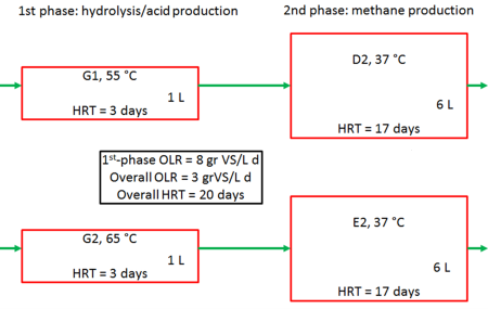
Anaerobic digestion usually takes place in one single reactor where all microbial degradation steps of the substrate to methane is carried out. This means that the acid-forming and methane-forming microorganisms are kept together in a single reactor system. It is a delicate balance between these two groups of organisms, since they differ widely in terms of physiology, nutritional needs, growth kinetics and sensitivity to environmental conditions. Thus, a physical separation of acid-formers and methane-formers in two separate reactors might lead to a more stable and efficient biogas process. To investigate this, two-phase biogas systems was set up at the biogas laboratory at Ås campus (see Figure 2).
|
Figure 2: Setup of anaerobic digestion two-phase system. HRT= Hydraulic retention time. |
Since hydrolysis and acid production is much faster than methane production, the 1st phase reactor was smaller (1L) than the 2nd phase reactor (6L). With a substrate (food waste) flowrate of 0.35 L/d this meant a hydraulic retention time (HRT) of 3 and 17 days for the 1st and 2nd reactors, respectively. The 1st phase reactor was run at thermophilic temperatures, while the 2nd phase was at mesophilic temperature. Two 2-phase systems were investigated where the only difference were the temperature in the thermophilic reactors (G1 and G2).
The two reactor set ups were run stably for 120 days, and both systems performed very similar. As expected the pH in the phase one reactors (G1, G2) were low (5.6-5.8), while the 2nd phase methane producing reactors (D2, E2) had a relatively high pH (7.9-8.1). The 1st phase reactors had a high soluble COD around 16 g/l, which was efficiently reduced (and converted to biogas) in the 2nd phase to around 1.5 g/L. Overall, both set-ups converted 78 % of the organic material to biogas.
Work is now in progress to characterise the microbial communities in the 4 reactors. It is expected very different and specialised populations in 1st phase and 2nd phase reactors. The 10 °C temperature difference in G1 and G2 did not affect performance of the reactors, but might affect the composition of the microbial communities. Finally, we will compare the performance of 2-phase system with a single-phase system, both about biogas production and microbial community composition.
WP2.5 - KMB STOP: Torrefaction
In 2013, the CenBio spin-off project KMB STOP (STable OPerating conditions in biomass combustion plants) was completed, and in 2014 the STOP-financed PhD study was completed, with PhD defense in January 2015. The PhD study with the title "Wet torrefaction of biomass - Production and conversion of hydrochar" focused on torrefaction in water, so-called wet torrefaction.
Wet torrefaction (WT) is a promising method for pretreatment of biomass for use as fuel. The method involves the use of hot compressed water, within 180–260 °C approximately, as reaction medium. Like dry torrefaction (DT), which may be defined as mild thermal treatment of biomass within 200–300 °C, WT improves significantly the fuel properties of biomass. In addition, due to the use of water as reaction medium, WT is highly suitable for low cost biomass sources such as forest residues, agricultural wastes, and aquatic energy crops, which normally have very high moisture content.
The PhD candidate, Quang-Vu Bach, focused on fuel properties improvements during wet torrefaction, also in comparison with dry torrefaction. A number of publications have been written during the PhD work, whereof the following were included in the PhD thesis:
- Quang‐Vu Bach, Khanh‐Quang Tran, Roger A. Khalil, Øyvind Skreiberg, Gulaim Seisenbaeva. Comparative assessment of wet torrefaction. Energy & Fuels 2013, 27, 6743‐6753.
- Quang‐Vu Bach, Khanh‐Quang Tran, Øyvind Skreiberg, Roger A. Khalil, Anh N. Phan. Effects of wet torrefaction on reactivity and kinetics of wood in air combustion. Fuel 2014, 137, 375‐383.
- Quang‐Vu Bach, Khanh‐Quang Tran, Øyvind Skreiberg, Thuat T. Trinh. Effects of wet torrefaction on pyrolysis of woody biomass fuels. Energy 2015, 88, p. 443-456.
- Quang‐Vu Bach, Khanh‐Quang Tran, Øyvind Skreiberg. Torrefaction of forest residues in subcritical water. Submitted.
- Quang‐Vu Bach, Khanh‐Quang Tran, Roger A. Khalil, Øyvind Skreiberg. Effects of CO2 on wet torrefaction of biomass. Energy Procedia 2014, 61, 1200-1203.
- Quang‐Vu Bach, Nevena Mišljenović, Khanh‐Quang Tran, Carlos Salas‐Bringas, Øyvind Skreiberg. Influences of wet torrefaction on pelletability and pellet properties of Norwegian forest residues. Annual Transactions ‐ The Nordic Rheology Society 2014, 22, 61‐68.
The major findings from the studies reported in the PhD thesis are:
- Both reaction temperature and holding time have significant effects on the mass yield, energy yield, and fuel properties of the hydrochar.
- Pressure also enhances the torrefaction rate; however, the effect becomes marginal above a certain pressure.
- Feedstock particle size slightly affects the yield and fuel properties of the hydrochar.
- Ash content of biomass fuel is significantly reduced by WT. Given the same solid yields, WT requires significantly lower torrefaction temperatures and shorter holding times than DT.
- Given the same solid yields, solid biomass fuels upgraded via WT have greater heating values than via DT.
- Hardwood is more reactive and produces less hydrochar than softwood in identical WT conditions.
- Forest residues are more reactive than stem woods in identical WT conditions.
- WT in CO2 enhances the torrefaction process, but reduces the heating value of hydrochar, compare to WT in N2.
- Overall, WT has positive effects on the fuel properties of biomass.
The interested reader can find more information in the PhD thesis:
Associate Professor Khanh-Quang Tran at NTNU has been the main supervisor while Chief Research Scientist Øyvind Skreiberg at SINTEF Energy Research has been the co-supervisor, and the STOP project leader.
After defending this thesis, Quang-Vu Bach has been very active, continuing with finalising submitted publications as well as producing several new ones based on experimental results from his PhD work. These are:
- Bach, Quang Vu; Tran, Khanh-Quang; Skreiberg, Øyvind. Combustion kinetics of wet-torrefied forest residues using the distributed activation energy model (DAEM). In press in Applied Energy. 2016
- Bach, Quang Vu; Tran, Khanh-Quang; Skreiberg, Øyvind. Comparative study on the thermal degradation of dry- and wet-torrefied woods. In press in Applied Energy. 2016
- Tran, Khanh-Quang; Trinh, Trung Ngoc; Bach, Quang Vu. Development of a biomass torrefaction process integrated with oxy-fuel combustion. Bioresource Technology 2016. vol. 199.
- Bach, Quang Vu; Skreiberg, Øyvind. Upgrading biomass fuels via wet torrefaction: A review and comparison with dry torrefaction. Renewable & Sustainable Energy Reviews. 2015 vol. 54.
- Bach, Quang Vu; Tran, Khanh-Quang. Dry and wet torrefaction of woody biomass – A comparative study on combustion kinetics. Energy Procedia. 2015 vol. 75.
- Bach, Quang Vu; Tran, Khanh-Quang. Wet Torrefaction of forest Residues – Combustion Kinetics. Energy Procedia. 2015 vol. 75.
- Bach, Quang Vu; Tran, Khanh-Quang; Skreiberg, Øyvind. Accelerating wet torrefaction rate and ash removal by carbon dioxide addition. Fuel processing technology. 2015 vol. 140.
- Bach, Quang Vu; Tran, Khanh-Quang; Skreiberg, Øyvind. Hydrothermal pretreatment of fresh forest residues: Effects of feedstock drying. Biomass & Bioenergy. 2016 vol. 85. p. 76-83.
During the 4 years of torrefaction research in STOP and CenBio, a large amount of research has been carried out. The results, the lessons learned and the prospects of torrefaction have been summarised in the STOP handbook, shown in Figure 1, available at the STOP webpage, where an up to date publications list from the STOP project is available.

|
Figure 1: The STOP handbook. (Illustration: SINTEF/Kjetil Strand) |