|
Classes |
| class | ChanVeseForce |
| | This ForceGenerator creates a normal force field, that leads to a segmentation similar to the model proposed by Chan and Vese. More...
|
| class | UpdatableImage |
| | Display the pixel distribution of the image as a graph (histogram).Graphical display of an Image, with basic user interaction functionality. More...
|
| class | ConstantForce |
| | This ForceGenerator creates a constant normal force, which does not depend on the underlying image or its current segmentation. More...
|
| class | ForceGenerator |
| | This is the abstract base class for the generators that define the normal force driving the evolution of a Region's LevelSetFunction. More...
|
| class | Histogram |
| | Class representing a histogram. Its main use is in the ParzenDistributionForce class. More...
|
| class | Image |
| | An 1, 2 or 3-dimensional image with an arbitrary number of channels. More...
|
| class | LevelSetFunction |
| | A class representing a level-set function in 1, 2 or 3D. More...
|
| class | MRBalloonForce |
| | This ForceGenerator creates a normal force field, which does not depend on the underlying image, only on its current segmentation. More...
|
| class | NormalDistributionForce |
| | This ForceGenerator creates a normal force field derived from the minimization of the Mumford-Shah functional, in a setting where each region is modeled statistically using a normal distribution. More...
|
| class | ParzenDistributionForce |
| | This ForceGenerator creates a normal force field derived from the minimization of the Mumford-Shah functional, in a setting where the pixel distribution of each region is modeled by a parzen estimate. More...
|
| struct | Region |
| | This struct represents the information completely describing one particular segmented region of an image. It can be used alone in a two-region segmentation setting (the other region being its complement), or several Regions can be used in a multiregion segmentation setting. More...
|
Typedefs |
| typedef Image< char > | Mask |
| | The Mask is an Image used for defining active and inactive pixels of another, identically shaped image.
|
Enumerations |
| enum | BorderCondition { DIRICHLET = 0,
NEUMANN = 1
} |
| | An enumeration of possible border conditions when solving a PDE. More...
|
| enum | SEG_REGION { SEG_NEGATIVE = 0,
SEG_POSITIVE
} |
Functions |
| void | load_image (const char *name, Image< double > &target, bool convert_to_greyscale=false) |
| | load an Image<double> from file
|
| void | load_image (const char *name, Image< int > &target, bool convert_to_greyscale=false) |
| | load an Image<int> from file
|
| void | save_image (const char *name, const Image< double > &target) |
| | save an Image<double> to file
|
| void | display_image (const Image< double > &img, int z=0) |
| | Display an image in a graphical window and pause the program until the window is closed.
|
| void | permanent_display (const Image< double > &img) |
| | Display an Image in a graphical window an continue execution of program.
|
| void | blur_image (Image< double > &img, double rho) |
| | Gaussian blur an Image<double> with a certain strength.
|
| void | blur_1D (double *data, unsigned int data_size, double rho) |
| | Gaussian blur an 1D-array of double values with a certain strength.
|
| void | gaussian_noise (Image< double > &img, double sigma=0) |
| | fill an Image<double> with Gaussian noise.
|
| void | compute_squared_gradient_sum_2D (const Image< double > &image, Image< double > &result) |
| | Compute an estimate of the squared gradient norm, for each pixel in a two-dimensional image.
|
| void | compute_squared_gradient_sum_3D (const Image< double > &image, Image< double > &result) |
| | Compute an estimate of the squared gradient norm, for each pixel in a three-dimensional image.
|
| void | analytic_eigvals (double alpha1, double alpha2, double alpha3, double beta, double gamma, double delta, double &lambda1, double &lambda2, double &lambda3) |
| | Compute the eigenvalues of a 3x3 symmetric matrix by analytically solving the corresponding characteristic polynomial.
|
| void | analytic_eigsys (double alpha1, double alpha2, double alpha3, double beta, double gamma, double delta, double &lambda1, double &lambda2, double &lambda3, double *v1, double *v2, double *v3) |
| | Compute the eigenvalues and eigenvectors of a 3x3 symmetric matrix by analytically solving the corresponding characteristic polynomial to find the eigenvalues, and then explicitly constructing the corresponding eigenvectors.
|
| void | numeric_eigsys (double alpha1, double alpha2, double alpha3, double beta, double gamma, double delta, double &lambda1, double &lambda2, double &lambda3, double *v1, double *v2, double *v3) |
| | Compute the eigenvalues and eigenvectors of a 3x3 symmetric matrix by means of an iterative numerical algorithm using Householder transformations and Givens rotations.
|
| void | compute_structure_tensor_2D (const Image< double > &img, Image< double > &G, bool square_root=false) |
| | Compute the structure tensor of a 2D-image, and writes the result to a 3-channeled 2D-image of the same resolution.
|
| void | compute_structure_tensor_3D (const Image< double > &img, Image< double > &G, bool square_root=false) |
| | Compute the structure tensor of a 3D-image, and writes the result to a 6-channeled 2D-image of the same resolution.
|
| void | compute_scale_factor_2D (const Image< double > &img, Image< double > &scale_accum, Image< double > &time_accum, double dt, double T) |
| void | compute_scale_factor_3D (const Image< double > &img, Image< double > &scale_accum, Image< double > &time_accum, double dt, double T) |
| void | nonlinear_gauss_filter_2D (const Image< double > &img_old, Image< double > &img_new, double dt, double sigma, double p) |
| void | nonlinear_gauss_filter_3D (const Image< double > &img_old, Image< double > &img_new, double dt, double sigma, double p) |
| void | anisotropic_smoothing (const Image< double > &img_old, Image< double > &img_new, double dt, double sigma, double p) |
| void | compute_smoothing_geometry_3D (const Image< double > &G, double p1, double p2, double p3, Image< double > &T, bool take_square_root) |
| void | compute_smoothing_geometry_2D (const Image< double > &G, double p1, double p2, Image< double > &T, bool take_square_root) |
| void | normal_direction_flow_2D (const LevelSetFunction &phi, LevelSetFunction &advect, BorderCondition bcond, double &H1, double &H2, const Mask *const changes_allowed_mask, const Mask *const defined_region_mask) |
| void | normal_direction_flow_3D (const LevelSetFunction &phi, LevelSetFunction &advect, BorderCondition bcond, double &H1, double &H2, double &H3, const Mask *const changes_allowed_mask, const Mask *const defined_region_mask) |
| void | visualize_multisets (const LevelSetFunction **const images, int num_images, Image< double > &target, const int **const rgb_color) |
| int | visualize_level_set (const LevelSetFunction &img, Image< double > &target, double threshold, double outside_intensity, double curve_intensity, double interior_intensity, const Mask *const mask, double mask_intensity) |
| void | LIC_2D_FS (const Image< double > &src, const Image< double > &vec, Image< double > &target, double(*kernel_func)(double), const double dl, const double L) |
| void | LIC_3D_FS (const Image< double > &src, const Image< double > &vec, Image< double > &target, double(*kernel_func)(double), const double dl, const double L) |
| void | LIC_3D (const Image< double > &src, const Image< double > &vec, Image< double > &target, double(*kernel_func)(double), const double L) |
| void | LIC_2D (const Image< double > &src, const Image< double > &vec, Image< double > &target, double(*kernel_func)(double), const double L) |
| double | develop_multiregion_2D (Region *regs, int num_regs, int num_iter, int reinit_modulo, const Mask *geom_mask) |
| double | develop_multiregion_3D (Region *regs, int num_regs, int num_iter, int reinit_modulo, const Mask *geom_mask) |
| void | negate (Image< double > &img, double min=0, double max=255) |
| | make an Image<double> a negative of itself.
|
| void | rescale (Image< double > &img, double cur_min, double cur_max, double to_min=0, double to_max=255) |
| | rescale the pixel range of an Image<double> so that its pixels spans a different range than before rescaling
|
| void | rescale_channels (Image< double > &img, double to_min=0, double to_max=255) |
| | rescale the pixel ranges of each of an image's channels to a user-specified interval
|
| void | clip (Image< double > &img, double min, double max) |
| | clip the pixel range of a image to a certain interval
|
| void | transpose (Image< double > &img) |
| | transpose the x and y dimensions of an Image<double>
|
| void | transpose (const Image< double > &img, Image< double > &target) |
| | Generate an Image<double> that is the transpose of another Image<double>.
|
| void | horizontal_sinusoidal_bands (LevelSetFunction &img, int num_bands, double phase=0) |
| | Initializes a LevelSetFunction with horizontal bands created by a sine function.
|
| void | rectangle (LevelSetFunction &img, double xmin_ratio, double xmax_ratio, double ymin_ratio, double ymax_ratio, double zmin_ratio=0, double zmax_ratio=1) |
| | Initializes a LevelSetFunction to become 1 everywhere, except for an interior rectangular domain where the LevelSetFunction has the value -1.
|
| void | init_voronoi_regions (LevelSetFunction *regs, const double *center_coords,int num_regions, bool three_d=false) |
| | Initializes a set of LevelSetFunctions defined on a common domain so that their closed regions together constitute a voronoi subdivision of the domain. The points defining the voronoi subdivision is given by the user.
|
| void | multiregion_bands (LevelSetFunction *regs, int num_regs, int pixel_bandwidth) |
| | Initializes a set of LevelSetFunctions defined on a common domain so that their closed regions together constitute a subdivision on the domain, and where each such region consists of a set of horizontal bands of a certain width along the y-direction.
|
| void | random_scattered_voronoi (LevelSetFunction *regs, int num_regs, int num_fragments) |
| | Initializes a set of LevelSetFunctions defined on a common domain so that their closed regions together constitute a voronoi subdivision of the domain. The points defining the voronoi subdivision are randomly generated.
|
| void | set_from_parzen (LevelSetFunction &img, const ParzenDistributionForce pf, const Mask *m=0) |
| | Initializes a LevelSetFunction to become a function with two values, 1 and -1, corresponding to the domains in which the force defined by the pf argument is positive or negative.
|
| void | sphere (LevelSetFunction &img, double relrad,double xrelpos,double yrelpos,double zrelpos=0) |
| | Initializes a LevelSetFunction to become the signed distance function from a point  in its domain minus some fixed value, thus its zero-set becomes a circle around . in its domain minus some fixed value, thus its zero-set becomes a circle around .
|
| void | make_border_mask (const LevelSetFunction &phi, Mask &target, int width=2, const Mask *geom_mask=0) |
| | Generate a Mask over a domain, where the active region of the Mask is specified as the region of a certain width (in pixels) around the zero-set of a LevelSetFunction defined on the same domain.
|
| void | mask_from_segmentation (const LevelSetFunction &phi, Mask &target, SEG_REGION reg) |
| | Generate a Mask over a domain, where the active region of the Mask is specified as the region defined by the negative (or positive) region of a LevelSetFunction over the same domain.
|
| void | read_image_sequence (istream &image_list, Image< double > &result, bool convert_to_grayscale) |
| unsigned long int | nonzeroes (const Image< int > &img) |
| | Count the number of nonzero pixels of an Image<int>.
|
| double | nonzero_ratio (const Image< int > &img) |
| | Calculate the ratio of the number pixels with a nonzero value to the total number of pixels in an Image<int>.
|
| unsigned long int | positives (const Image< double > &img) |
| | Count the number of pixels with a nonnegative value in an Image<int>.
|
| unsigned long int | negatives (const Image< double > &img) |
| | Count the number of pixels with a negative value in an Image<int>.
|
| double | positive_ratio (const Image< double > &img) |
| | Calculate the ratio of the number of pixels with a nonnegative value to the total number of pixels in an Image<double>.
|
| double | negative_ratio (const Image< double > &img) |
| | Calculate the ratio of the number of pixels with a negative value to the total number of pixels in an Image<double>.
|
| double | develop_single_region_2D (Region ®, int num_iter, int reinit_modulo, const Mask *geom_mask) |
| double | develop_single_region_3D (Region ®, int num_iter, int reinit_modulo, const Mask *geom_mask) |
| template<typename T> |
| void | combine_channel_images (const Image< T > **channel_array, int num_input_images, Image< T > &result) |
| template<typename T> |
| void | to_grayscale (Image< T > &img) |
| | convert a three-channel Image (RGB of double, int, etc.) to greyscale.
|
| void | read_image_sequence (std::istream &image_list, Image< double > &result, bool convert_to_grayscale=false) |
| | Read a set of 2D-image files and write the result into a 3D Image<double>, where the read images will be stacked along the z-coordinate direction.
|
| template<typename ImgType> |
| void | resample_into (const ImgType &src, ImgType &target, bool linear=true) |
| | Resample an image, using nearest-pixel or linear interpolation.
|
| template<typename ImgType> |
| void | downsample_series (const ImgType &input, std::vector< ImgType > &result, int min_num_pixels, bool downscale_z=false, double downscale_factor=2, bool to_grayscale=false, bool linear=true) |
| | Create a sequence of progressively smaller, resampled copies of a reference image.
|
Variables |
| const int | RED [] = {255, 0, 0} |
| | 3-tuple of int representing the color red in RGB format.
|
| const int | BLUE [] = {0, 255,0} |
| | 3-tuple of int representing the color blue in RGB format.
|
| const int | GREEN [] = {0, 0, 255} |
| | 3-tuple of int representing the color green in RGB format.
|
| const int | YELLOW [] = {255,0, 255} |
| | 3-tuple of int representing the color yellow in RGB format.
|
| const int | CYAN [] = {0, 255, 255} |
| | 3-tuple of int representing the color cyan in RGB format.
|
| const int | MAGENTA [] = {255, 255, 0} |
| | 3-tuple of int representing the color magenta in RGB format.
|
| const int | WHITE [] = {255,255, 255} |
| | 3-tuple of int representing the color white in RGB format.
|
| const int | BLACK [] = {0, 0, 0} |
| | 3-tuple of int representing the color black in RGB format.
|
| const int | GREY [] = {200, 200, 200} |
| | 3-tuple of int representing the color grey in RGB format.
|
| const int | BROWN [] = {200, 100, 40} |
| | 3-tuple of int representing the color brown in RGB format.
|
 parameter of the Gaussian kernel. Should be positive. The higher the value of
 ![\[ \left(\begin{array}{ccc} \alpha_1 & \beta & \gamma \\ \beta & \alpha_2 & \delta \\ \gamma & \delta & \alpha_3 \end{array} \right)\]](form_1.png)
 in the matrix above (first diagonal term)
  in the matrix above (second diagonal term)
  in the matrix above (third diagonal term)
  in the matrix above
  in the matrix above
  in the matrix above
 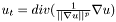 , where
  represent the image pixel values and
  is a fixed scalar value. An explanation can be found in section 2.1 of
  , where
  and
and  are the three eigenvectors of the
  ,
,  and
and  are computed from the eigenvalues of the structure tensor,
  ,
,  and
and  in the following way:
 ![\[c_1 = \frac{1}{(1 + \lambda_u + \lambda_v + \lambda_w)^{p_1}}\]](form_20.png)
![\[c_2 = \frac{1}{(1 + \lambda_u + \lambda_v + \lambda_w)^{p_2}}\]](form_21.png)
![\[c_3 = \frac{1}{(1 + \lambda_u + \lambda_v + \lambda_w)^{p_3}}\]](form_22.png)
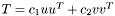 , where
 ![\[c_1 = \frac{1}{(1 + \lambda_u + \lambda_v)^{p_1}}\;,\;\;\;\;c_2 = \frac{1}{(1 + \lambda_u + \lambda_v)^{p_2}} \]](form_15.png)
 satisfying the CFL condition:
 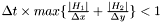 . The book
 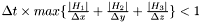 . The book
  to
to  , so that
  and
and  format (2D) or
  format (3D).