Facilities and instrumentation

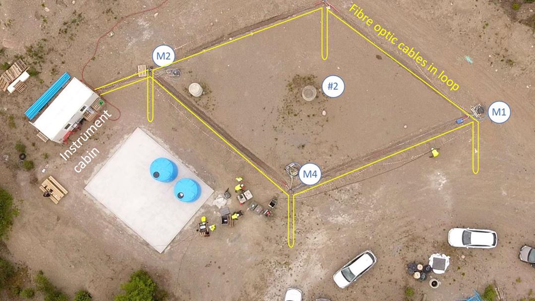
Svelvik CO2 Field Lab consists of an injection well and four monitoring wells. The injection well is designed for injecting water and/or CO2 at 64-65 meters depth. Tracers may be added to the CO2 stream. The four monitoring wells are 100 m deep and positioned at the corners of a rhombus with the injection well (#2) in the centre. The monitoring wells are located 9.9 m (M3 and M4) and 16.5 m (M1 and M2) from the injection well.
INSTRUMENTATION OF MONITORING WELLS
The monitoring wells (M1–M4) have instrumentation installed outside the casing making the inside of the casing available for non-permanent instrumentation and logging tools. Behind casing instrumentation includes:
- Pore pressure sensors in the injection layer (65 m depth) for three wells (M1–M3)
- Electrodes at 16 depths enabling cross-hole Electrical Resistivity Tomography (ERT) measurements
- Commercial fibre-optic cables (straight fibres) in a loop covering all four monitoring wells (see illustration)
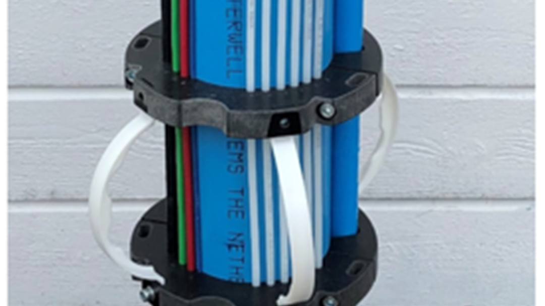
- Research fibre-optic cables (helical and straight fibres)
INSTRUMENTATION OF INJECTION WELL
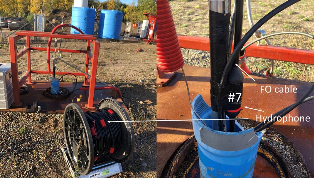
The injection well is completed to 65 m depth. An injection screen is installed between 64 and 65 m. The bottom of the injection packer is at 63 m. The packer is instrumented with sensors measuring the temperature and pressure of the injected gas/fluid at injection depth. The annulus between injection tube and casing is spacious enough to allow (temporary) installation of hydrophones, for more complex setups. Currently, a fibre-optic cable is installed in this annulus to record the signature of CO2 in the injection tubing and in the near-well area on geophysical monitoring data.


