Hjem til forsiden

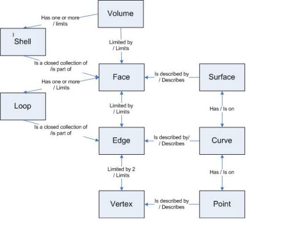
CAD boundary structures
Boundary structures were introduced for representing volumes in CAD-systems by Ian Braid [1] in his Ph.D. thesis from 1974. This triggered an extensive research in the second half of the 1970es and the 1980es into data structures for CAD.

Soon many CAD-systems included boundary structures. However, although the implementation followed the same basic ideas, the implementations were different and exchange of volume models between CAD-systems was almost impossible. The answer to this was first introduction of national standards and de facto industrial standards (such as VDA-FS, SET and IGES). However, by the end of the 1980es the STEP (ISO 10303) standard was introduced and a common data structure for exchange of CAD volume models was introduced.  

The boundary structure has two types of objects:

  • Topological objects:  Vertex, edge, loop, face, shell and volume
  • Geometric objects: Point, curve and surface

  Data structures describes how:

  • Volumes are bounded by shells
  • Shells are built by faces
  • Faces are limited by loop
  • Loops are built by edges
  • Edges are limited by vertices
  • Faces and surfaces are related
  • Edges and curves are related
  • Vertices and points are related

[1] Braid, I.C., Designing with volumes, Ph.D. Thesis, Cambridge University, England, (1974).

Published June 29, 2005