Hjem til forsiden

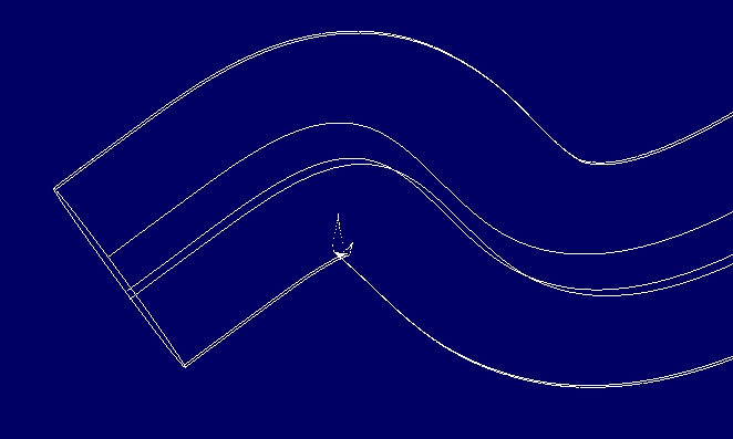
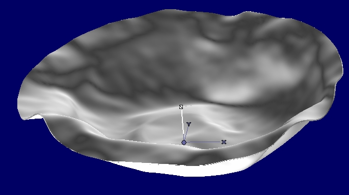
Self-intersection challenges
Operations such as lofting of surfaces, offset of surfaces and offset of structures of surface will sometimes produce self-intersecting surfaces, as will offset self-intersecting shells. Often the self-intersections will be large and easily detected by visual inspection. Sometimes minor editing of the input data can solve the problem. In other cases, expensive redesign or working around them is required. However, when the self-intersections are small they will easily remain in the CAD-model, later inducing problems when the CAD-model is used in applications such as simulation or production planning.
When producing moulds the side of the object to be moulded is often first designed as a surface or a patchwork of surfaces, then a constant or variable offset is made to produce the opposite side of the object. This offset operation often produces surfaces with many self-intersections, and as most CAD-systems do no detect self-intersections, the CAD-user has to manually design the offset surface.

Tube with self-intersection Tube with self-intersection Tube with self-intersection

The image to the left shows a face geometry to be offset. The picture in the middle shows the offset surface as seen from behind. Notice the self-intersections around the eyes. The picture to the right shows that the offset surface penetrates the original surface.

Published June 29, 2005

Tube with self-intersection

Tube with self intersection

Critical curves on tube indicating self-intersections

Critical curves on tube indicating self-intersection

Critical curves on tube indicating self-intersections

Due to the complexity of the surfaces, the user can not obtain an offset of the left model more than 3mm, otherwise the self-intersection appears.